
Propellers for F3D Models - Part 2 |
The propeller, with its unique characteristics, has to work together with the power curve of the engine as well as the drag polar of the airplane. When I started theoretical work on pylon racing model propellers, around 1982, there were already quite efficient propellers available, which had been developed by trial and error. Thus it was the first step to take some of these propellers and analyze their characteristics.
A Propeller from 1982 (designed for 18000 1/min)The first example shown here, had been a molded carbon/epoxy propeller of 9 inch diameter and a nominal pitch of 7.5 inch, provided by Otto Jakob. This sample was first measured to extract the planform and the twist distribution. |
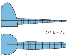 Geometry of a propeller for the OPS .40 Pylon engine, turning 18000 rpm on the ground (which was a restriction of the German national F3D rules in 1982). |
| Examining the Airfoils | Because we had no access to a special coordinate measuring machine, one blade was cut into 10 segments, which were embedded into a block of white resin, smoothed and polished. The block was then photographed and the resulting images enlarged to find the section coordinates. The airfoil sections are depicted below and show, that the shape was quite good, only the trailing edge was rather thick and blunt. It has to be noted, that the original propellers were manufactured by hand, without the usage of CNC machines. Also note, that their blade width length varies between 5 mm and 15 mm only, which makes it quite difficult to create something like an airfoil. |
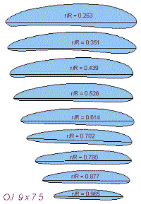 |
These airfoil sections were analyzed using Epplers PROFIL
code to get the lift and drag characteristics for each airfoil. The
results indicated, that the lift vs. drag polars looked quite good, but
the overall drag was almost twice as high as the drag of a perfect
airfoil. This was mainly due to the blunt trailing edge, which cannot be
improved very much if a practical propeller is desired.
Airfoils on the propeller for the OPS .40 Pylon. |
| Examining the Geometry | The twist of the propeller was measured on a standard propeller pitch
measuring gauge, and for the planform a slide gage was be used (more measuring
methods).
Together with the planform of the propeller blades these airfoil data were fed into my propeller analysis code PROPPY to calculate the thrust- and power-coefficients as well as the efficiency. The meaning of these coefficients are explained in the following section. |
Similar to airfoils and wings, the performance of propellers can be described
by dimensionless coefficients. While an airfoil can be characterized by
relations between angle of attack, lift coefficient and drag coefficient, a
propeller can be described in terms of advance ratio, thrust
coefficient, and power coefficient. The efficiency can be
calculated by: thrust divided by the consumed power multiplied
with the velocity of flight (all units cancel out). The normalized
coefficients are helpful for the comparison of geometrically similar propellers
of differing diameters.
Depending on the country where you live, there may be different coefficients in
use. All coefficients used here, are based on the publications of the NACA,
which defined the following coefficients:
| Thrust | ||
| Power | ||
| Advance Ratio | ||
| Efficiency | ||
| where | ||
| v | velocity | m/s |
| D | diameter | m |
| n | rotations per second | 1/s |
| density of air | kg/m³ | |
| P | power | W |
| T | thrust | N |
It should be noted, that the definition of the efficiency includes the velocity v. Thus the efficiency goes to zero when the flight speed approaches zero - of course, this does not mean, that the thrust goes to zero. Usually the power and thrust coefficients are plotted versus the advance ratio. The efficiency can be calculated from these values.
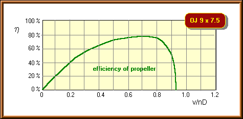
Calculated efficiency versus advance ratio v/nD of the example propeller. The
efficiency in flight will be up to 5% less that calculated due to installation
effects.
The next example represents the current (as of 1996) state of the art, as it is used for international F3D contests, without any speed limit. The examined propeller is called «Verano-Type» and seems to be modeled after a sample propeller of R. Verano - his genealogy could not be traced down to the very roots.
 |
Front view of the «Verano-Type» propeller. |
 |
Side view of the «Verano-Type» propeller. |
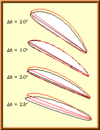 Four sections of the «Verano-Type» propeller. |
The left column shows the airfoils, as they are built into the two blades, but normalized to the same chord length. The image indicates, that there are differences in shape, as well as in blade angle. The black line corresponds to blade no. 1, whereas the red outline represents the sections of blade no. 2. The blade angle of the two blades shows differences between 1° and 2.5°. |
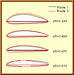 Airfoils of the «Verano-Type» propeller. |
The airfoil sections on the left, turned to a common x-axis, show large differences mainly in the outboard region of the blade. Obviously, too many finishing touches with sand paper have been applied here. The sections of blade no. 2 (red line) show a more promising shape than the sections of blade 1. Again, these airfoil sections were analyzed to find their aerodynamic characteristics. Finally the resulting polars and the propeller geometry was fed into the propeller analysis code and two analysis runs were performed. The first one for the geometry of blade 1, the second run was made with the geometry of blade 2. The performance of the real propeller can be expected to fall somewhere in between these two results. The propellers aerodynamic coefficients are depicted below. |
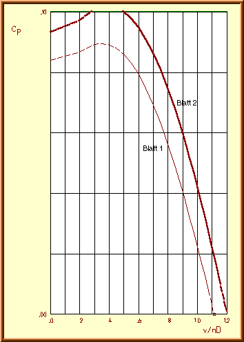
Power coefficient![]() of
the «Verano-Type» propeller vs. advance ratio v/nD.
of
the «Verano-Type» propeller vs. advance ratio v/nD.
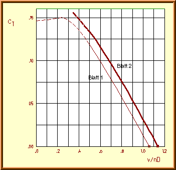
Thrust coefficient![]() of
the «Verano-Type» propeller vs. advance ratio v/nD.
of
the «Verano-Type» propeller vs. advance ratio v/nD.
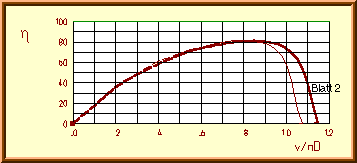
Efficiency ![]() of
the «Verano-Type» propeller vs. advance ratio v/nD.
of
the «Verano-Type» propeller vs. advance ratio v/nD.
During flight, propeller, model and engine performance are closely connected. The propeller absorbs the engine's power and its thrust overcomes the model's drag. To find an operating point, given a propeller, an engine and a model with their respectively characteristics:
If you have prepared the drag characteristics R versus v of your model for various climb angles, you can find out the flight speed for each climb angle and also the maximum climb rate. The section how it works together shows an example for a pylon racing model in level flight.
As most of the basic theoretical fundamentals, the theory of optimum propellers has been developed quite early in aviation history. The most important work was probably that of Prandtl and Betz in the 1920s. Based on their mathematical models, it was possible to describe the aerodynamic conditions for propellers and windmills with minimum induced losses. With the rapid development of the jet engine after 1945, the knowledge about propellers was shrinking rapidly. In the 1970s, people like Larrabee [11], Adkins [10] and probably some more, dug out the old papers and built computer programs to design optimum propellers. If you read their papers, you will find that the basic formulas are astonishingly simple - in fact my first trial code, based on a paper of Larrabee, was developed in 1984 using a HP-41C pocket calculator!
![]() Propellers
for F3D Models - Part 1
Propellers
for F3D Models - Part 1
![]() Propellers
for F3D Models - Part 3
Propellers
for F3D Models - Part 3
Last modification of this page: 15.10.07
![]()
[Back to Home Page] Suggestions? Corrections? Remarks? e-mail: Martin Hepperle.
Due to the increasing amount of SPAM mail, I have to change this e-Mail address regularly. You will always find the latest version in the footer of all my pages.
It might take some time until you receive an
answer and in some cases you may even receive no answer at all. I apologize for
this, but my spare time is limited. If you have not lost patience, you might
want to send me a copy of your e-mail after a month or so.
This is a privately owned, non-profit page of purely educational
purpose. Any statements may be incorrect and unsuitable for practical usage. I
cannot take any responsibility for actions you perform based on data,
assumptions, calculations etc. taken from this web page.
© 1996-2008 Martin Hepperle
You may use the data given in this document for your personal use. If you use
this document for a publication, you have to cite the source. A publication of a
recompilation of the given material is not allowed, if the resulting product is
sold for more than the production costs.
This document may accidentally refer to trade names and trademarks, which are owned by national or international companies, but which are unknown by me. Their rights are fully recognized and these companies are kindly asked to inform me if they do not wish their names to be used at all or to be used in a different way.
This document is part of a frame set and can be found by navigating from the entry point at the Web site http://www.MH-AeroTools.de/.