Propellers for F3D Models - Part 1 |
The propeller has the task to transform the power of the engine into thrust in the most efficient way. Due to the high rotational speed, and the high power to absorb, propellers for pylon racing engines usually are made from wood or composite material. Most injection molded propellers cannot sustain the high loads which makes them insecure and dangerous. When propellers are made from composite materials (epoxy resin and carbon/glass/kevlar rovings), moulds are used which permit a very accurate reproduction of the master propeller. Wooden propellers are lighter and reduce the vibration levels, but are more delicate to handle and cannot easily be duplicated. Also composite materials are better suited for the rather thin airfoils near the propeller tips.
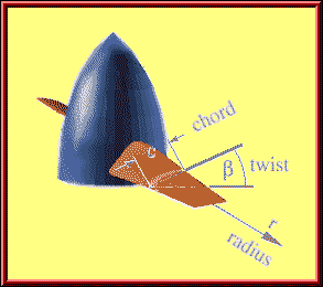
| For the following discussion it is necessary to define a description of
the propeller geometry. Similar to a wing, a propeller can be defined by one
overall dimension (the Diameter D) and local dimensions like the
chord length c and the local blade angle (twist) ß (a
lower case Greek beta), which are depending on the radial position r.
In contrast to a wing, a propeller shows a strong variation of the twist distribution along the radius. The local inflow, seen by a segment of the propeller consists of two parts:
|
 Parameters used for the description of the propeller geometry. |
 Flow components, as seen by a blade section of a propeller. The local flow vector is composed of a rotational (here: horizontal) and an axial component. |
The rotational component depends on the rotation speed and the
radial position, where the blade section is located; at the axis this
component is zero, whereas at the wing tip (r = D/2) it reaches its
maximum value of
The total velocity is the sum of the axial and the rotational component:
|
|
The graph above can be used to find the tip speed and Mach number for given propeller diameters and flight speeds. The example shows the three steps to use it:
For the example (21500 1/min, diameter 128 mm, flight speed 100 m/s) we find a tip speed of about 175 m/s or just above Mach 0.5. |
|
| Example: | On the ground, with vaxial = 0.0,
a propeller having a diameter of D = 0.18 m and rotating at rpm
= 25000 1/min reaches a tip velocity of:
3.1415926 * (25000/60) * 0.18 = 235.6 m/s. If the plane flies at a speed of 60 m/s, the tip speed increases to
Because the speed of sound is approximately 340 m/s, this tip speed equals Mach 0.715. |
 A propeller, slicing through a dense medium and advancing by «pitch» per revolution. |
Instead of the twist or blade angle
distribution, the term pitch is often used. The pitch of a metal
screw is the distance, the screw would travel through its nut in axial
direction, when it performs one rotation. Unfortunately, this is only valid
for a perfect screw, mathematically a helix, which has the same
pitch all along the radius, otherwise the screw would get stuck.
Propellers usually do not have a constant pitch along the radius, so that a given pitch is only an approximate measure to describe a propellers geometry. Comparing the pictures above and at the left hand side, we can calculate the pitch P of the inflow at the propellers tip: v / (pi*n*D) = P / (pi*D) = pitch / circumference of one rotation, which can be solved for P to be P = v/n. A practical propeller must have at least the calculated pitch of the onset flow to create thrust. |
 The flattened outside surface of the cylinder above, showing the pitch triangle and the inflow angle phi. Also shown is the triangle, corresponding to a different radius station r, which has the same pitch, and thus a larger pitch angle phi. |
Using the helix model, we can also calculate the pitch angle
phi at any radial station. Since all stations must advance the same
distance per revolution, they must also have the same pitch. Because the
circumferential distance per revolution depends on the radius station, the
pitch angle must increase, when we move from the tip towards the root.
Finally, at the axis of rotation, where the local radius is zero, the pitch
angle must be 90° to match the prescribed pitch.
We can find the pitch angle graphically, by plotting the geometry of the pitch triangles, or we can calculate it by basic trigonometry for any radial station r from phi(r/R) = arctan ( v / (pi*n*D*r/R) ). (arctan is the inverse tangent function, found on all scientific pocket calculators as atan, inv tan or tan -1). |
| Example: | The incoming flow of the plane from the example above, flying at a speed
of v=60 m/s, hits the propellers tip with a pitch of approximately
P = 60 m/s / (25000 / 60 s) = 0.144 m (=5.7 inch). We should look for a propeller with a pitch of 6 to 6.5 inch. The inflow angle at the tip will be phi_tip = arctan(v / (pi*n*D)) = arctan ( 60 / (3.1415*25000/60*0.18) ) = 14.3°, but at 50% of the radius, we will have an angle of phi_50% = arctan(v / (pi*n*D*0.5)) = arctan ( 60 / (3.1415*25000/60*0.18*0.5) ) = 27.0°, and at 25% of the radius, the helix angle will become phi_25% = arctan(v / (pi*n*D*0.25)) = arctan ( 60 / (3.1415*25000/60*0.18*0.25) ) = 45.5°. |
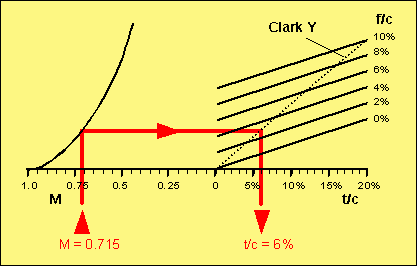
Due to the high Mach number, compressibility effects (recompression shocks, causing additional drag) reduce the efficiency of the propeller. A practical way to keep the drag of an airfoil at acceptable levels is the use of thinner and less cambered airfoils. To avoid excessive drag, a certain critical camber and thickness should not be exceeded. The Mach number, at which the flow reaches supersonic speed at some point on the airfoil, is called the critical Mach number. Sometimes it might be acceptable to have a small supersonic region at the propeller tip, because a reduction of the diameter (to avoid supersonic tips) also decreases the performance. But in general, a propeller should be designed to avoid supersonic flow by choosing the right airfoil «thin-ness» and the right diameter. The analysis of compressibility effects on propeller performance is a very complex matter, and cannot be handled here, but, concluding from experimental data, it is possible to develop a rule of thumb. The figure below can be used to find the maximum allowable thickness and camber for a given Mach number and vice versa.

Diagram showing correlations between critical Mach number and airfoil
geometry.
| Example: | For our example, we assume that the propeller has a Clark Y like airfoil (flat lower side), which means, that the camber is approximately half the airfoil thickness. Using the result from above, with a tip Mach number of M = 0.715, we enter the diagram at the left, draw a line straight up, until it meets the curved line. From the intersection, we draw a horizontal line up to the line corresponding to the camber of the airfoil. For the special case of Clark Y-like airfoils, we can also use the dotted line as an end point. Dropping down from this intersection, we find the maximum thickness to be 6%. If we choose a thicker section, we will reach supersonic flow at the propeller tip, degrading the performance. If the chord length at the tip is 10 mm, the airfoil there should have a thickness of 0.6 mm, which is quite difficult to manufacture and rather unpractical though. |
More:
![]() Propellers for F3D Models - Part 2
Propellers for F3D Models - Part 2
![]() Propellers for F3D Models - Part 3
Propellers for F3D Models - Part 3
Last modification of this page: 15.10.07
![]()
[Back to Home Page] Suggestions? Corrections? Remarks? e-mail: Martin Hepperle.
Due to the increasing amount of SPAM mail, I have to change this e-Mail address regularly. You will always find the latest version in the footer of all my pages.
It might take some time until you receive an
answer and in some cases you may even receive no answer at all. I apologize for
this, but my spare time is limited. If you have not lost patience, you might
want to send me a copy of your e-mail after a month or so.
This is a privately owned, non-profit page of purely educational
purpose. Any statements may be incorrect and unsuitable for practical usage. I
cannot take any responsibility for actions you perform based on data,
assumptions, calculations etc. taken from this web page.
© 1996-2008 Martin Hepperle
You may use the data given in this document for your personal use. If you use
this document for a publication, you have to cite the source. A publication of a
recompilation of the given material is not allowed, if the resulting product is
sold for more than the production costs.
This document may accidentally refer to trade names and trademarks, which are owned by national or international companies, but which are unknown by me. Their rights are fully recognized and these companies are kindly asked to inform me if they do not wish their names to be used at all or to be used in a different way.
This document is part of a frame set and can be found by navigating from the entry point at the Web site http://www.MH-AeroTools.de/.