When the airfoil is located in a stream of air of velocity
For the following explanations it is assumed, that a stream of air is directed against an airfoil, which is fixed in space. This is equivalent to an airfoil moving through the air - just a question of the reference system. A typical wind tunnel works in the same way.
Instead of looking at a wing, we will simplify our model to two dimensions by
building a wing of very large span (infinite, if we have enough material...) and
by looking at a section close to the center of this wing: the result is a two
dimensional airfoil.
When the airfoil is located in a stream of air of velocity
![]() , the flow has to part near the
leading edge and pass along the upper and the lower airfoil surface. At the
location, where the flow is splitting up, the flow velocity is reduced to zero.
This point is called stagnation point. It is located close to the
leading edge of the airfoil, but its position moves with angle of attack.
, the flow has to part near the
leading edge and pass along the upper and the lower airfoil surface. At the
location, where the flow is splitting up, the flow velocity is reduced to zero.
This point is called stagnation point. It is located close to the
leading edge of the airfoil, but its position moves with angle of attack.

Velocity distribution plot for both surfaces of the Eppler E 64 airfoil at 2
degrees angle of attack
(result from Eppler's high order panel method).
Let us follow the flow from the stagnation point, along both sides of the Eppler E 64 airfoil at 2º angle of attack, as shown above:
Velocity and pressure are dependent on each other - Bernoulli's equation says that increasing the velocity decreases the local pressure and vice versa. Thus the higher velocities on the upper airfoil side result in lower than ambient pressure whereas the pressure on the lower side is higher that the ambient pressure. It is possible to plot a pressure distribution instead of the velocity distribution (usually not the pressure, but the ratio of the local pressure to the stagnation pressure is plotted and called pressure coefficient Cp):
 .
.
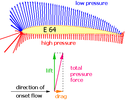
Summing up the pressure acting on the airfoil results in a total pressure force. Splitting up this total pressure force into a part normal to the flow and another one tangential to the flow direction, results in a lift force L and a drag force D. In some regions, the pressure force acting on the airfoil is of lower pressure than the surrounding pressure and in other regions, it is higher. The following image shows the pressure forces for the E64 at 2° angle of attack. It also shows, how the total force is split into lift and drag forces (the drag force due to pressure is usually very small, see below). The figure also shows, that most of the lift is caused by the low pressure area above the wing.

Pressure force distribution the surface of the Eppler E 64 airfoil at 2
degrees angle of attack
(result from Drela's XFoil code).
If we had used a symmetrical airfoil at no incidence, the distribution of
velocity and thus the pressures along both surfaces would have been exactly the
same, canceling each other to a resulting total lift force of zero. The
calculation of the forces can be performed by summing (math: integrating)
the pressure distribution of a plot of Cp versus chord. The total force
corresponds to the area enclosed between the curves for the upper and the lower
surface. It is easy to transform Bernoullis equation, written once for a point
in space far away from the airfoil (where the velocity is
![]() ) and once for a
point on the airfoil (velocity v) to arrive at the actual pressure p
on the surface of the airfoil:
) and once for a
point on the airfoil (velocity v) to arrive at the actual pressure p
on the surface of the airfoil:
 .
.
In general an airfoil does not only create a lifting force, it also creates a moment, which tries to rotate the airfoil to a different, angle of attack. For comparisons it is generally assumed that the lift force and this torque moment are acting at a fixed point, which is located 25% behind the leading edge on the x-Axis (often called «¼ chord point»). Typical cambered airfoils create a moment, which tries to reduce the angle of attack (pitch down) - by definition its sign is negative. The moment acting at the ¼ chord point is nearly independent of angle of attack, as long as the flow stays attached to the airfoil.
If no separation or compressibility effects are present, the pressure field around a two dimensional airfoil creates a lifting force only, no drag. The drag of a two dimensional airfoil is created by the friction of the air particles moving close to the surface. The airfoil is surrounded by a boundary layer, which forms a thin sheet adjacent to the wall where the velocity is reduced from the free stream value down to zero on the wall. For the theoretical treatment of lift, the boundary layer effect is so small that it can be neglected as long as no separation occurs; this applies also (albeit to a lesser degree) to the moment of the airfoil. But the boundary layer is the main source for the drag in two dimensional flow (airfoils).
The lift, drag and moment of a wing depends not only on the airfoil shape and its associated velocity distribution, but also on wing planform and on the wing area. Experiments show, that doubling the wing area or the fluid density also doubles lift and drag, but doubling the air speed yields four times as much lift. The forces and moments also depend on the density of the air and on the shape of the wing. It is possible to compare the aerodynamic properties of differently sized airfoils or wings, if all forces and moments are normalized. These dimensionless properties (coefficients) are defined as follows:
| Lift Coefficient |
|
| Drag Coefficient |
|
| Moment Coefficient |
|
Knowing these coefficients for a certain airfoil section at a certain angle
of attack, makes it possible to calculate the forces acting on wing sections of
different sizes, mounted between walls at different flow velocities and air
densities, but at the same angle of attack. To calculate the lift of a "real
wing", the local flow conditions, which change from root to tip, have to be
taken into account although.
For "real wings" and aircraft the same coefficients are used, but the lower case
identifiers l, d, and m are replaced by upper case
characters L, D and M. If these coefficient are known
for an aircraft, the total forces and moments for the complete aircraft can be
calculated for different flow conditions.
| Example: | Wind tunnel tests of an ultra-light aircraft gave a lift coefficient
CL = 0.1 at 0° angle of attack. What is
the lift force L on the full scale aircraft, which has a wing area
S of 12 m², at an air speed v of 252 km/h
? The air speed of the full scale aircraft in SAE units is 252/3.6 = 70 m/s. We assume the density of air to be For a quarter scale model, flying at half the speed, we would obtain: |
For each angle of attack, the flow field around an object changes.

Surface velocity distribution of the NACA 2412 airfoil at 0º angle of
attack.
The difference between the velocities on the upper and lower side of the NACA 2415 airfoil at 0º angle of attack is relatively small. The enclosed area corresponds to the integrated pressure difference and results in a small lifting force.

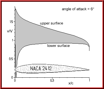
Velocity distribution on the surface of the NACA 2412 airfoil at 6º angle of
attack.
Increasing the angle of attack to 6º also changes the velocity distribution: The velocity on the upper surface increases, whereas the velocity on the lower surface is reduced. The enclosed area increases and thus the lift (-coefficient). The differences are more pronounced in the leading edge region, which (in this case) contributes most to the total lift.
The image also shows, that the stagnation point (where the velocity is zero)
is not exactly located at the extreme left of the leading edge, but instead has
moved slightly back on the lower side. The streamlines passing along the upper
surface have to turn around the leading edge, whose small radius of curvature
accelerates the flow in this region rapidly (from zero to 100 in a split
second). This causes the velocity peak close to the leading edge, where the flow
reaches about 1.85 times the speed
![]() of the onset flow.
of the onset flow.
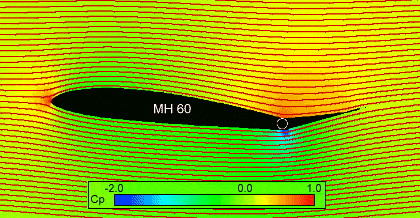
The pictures above showed, what can be calculated or measured on the surface of the airfoil. To get a better feeling, how the velocity in the vicinity of the airfoil looks like, the following image illustrates the flow field around the airfoil. The pressure changes, introduced by the airfoil, can be felt all around the airfoil, for subsonic flow even in front of the airfoil.
 |
Calculated flow field around the MH 60 airfoil with
-5.0º flap deflection at 6º angle of attack. The red stream traces show the
local flow direction. The background colors show the pressure field with
high pressures in red and low pressures (suction) in blue. The solution was calculated by solving the Euler equations using the proprietary »FLOWer« code. |
Due to the large, negative flap deflection, the `lifting´ force of the airfoil is directed downwards. The positive pressure near the leading edge (red, Cp = +1.0) indicates the location of the stagnation point, whose position can be assumed between the dividing streamlines. Another area of high pressure is visible on the upper surface in the concave corner, caused by the flap deflection. The convex corner on the opposite side of the flap causes high velocities and thus low pressure (blue). Both regions together are the main cause for a clockwise torsion moment, which results in a positive moment coefficient cm.
The videos show how changing the angle of attack or the deflection of a flap changes the flow field around an airfoil. It is interesting to note, that a flap deflection has a strong effect at the leading edge, not only at the trailing edge. This is why most commercial airplanes which use large flap deflections also use leading edge devices like slats or Krüger flaps to adapt the leading edge shape to the local flow direction. The last video "Angle of Attack 2") shows the relation between flow field and surface velocity distribution.
| AVI |
 |
MPEG | ||
 |
(160x120 AVI file, 0.804 MB) (same as ZIP file, 0.432 MB) |
Flap Deflection | (240x180 MPEG file, 0.685
MB) (same as ZIP file, 0.483 MB) |
 |
 |
(160x120 AVI file, 0.970 MB) (same as ZIP file, 0.583 MB) |
Angle of Attack 1 |
(240x180 MPEG file, 0.666
MB) (same as ZIP file, 0.486 MB) |
 |
| Angle of Attack 2 |
(240x180 MPEG file, 2.019
MB) (same as ZIP file, 1.604 MB) |
 |
||
You might love to see larger videos in higher resolution, but due to the current speed limits in the internet, I have tried to create videos with the smallest possible size without loosing too much of the aerodynamics. Although compressed, these files are still quite big.
Last modification of this page: 05.05.04
![]()
[Back to Home Page] Suggestions? Corrections? Remarks? e-mail: Martin Hepperle.
Due to the increasing amount of SPAM mail, I have to change this e-Mail address regularly. You will always find the latest version in the footer of all my pages.
It might take some time until you receive an
answer and in some cases you may even receive no answer at all. I apologize for
this, but my spare time is limited. If you have not lost patience, you might
want to send me a copy of your e-mail after a month or so.
This is a privately owned, non-profit page of purely educational
purpose. Any statements may be incorrect and unsuitable for practical usage. I
cannot take any responsibility for actions you perform based on data,
assumptions, calculations etc. taken from this web page.
© 1996-2006 Martin Hepperle
You may use the data given in this document for your personal use. If you use
this document for a publication, you have to cite the source. A publication of a
recompilation of the given material is not allowed, if the resulting product is
sold for more than the production costs.
This document may accidentally refer to trade names and trademarks, which are owned by national or international companies, but which are unknown by me. Their rights are fully recognized and these companies are kindly asked to inform me if they do not wish their names to be used at all or to be used in a different way.
This document is part of a frame set and can be found by navigating from the entry point at the Web site http://www.MH-AeroTools.de/.